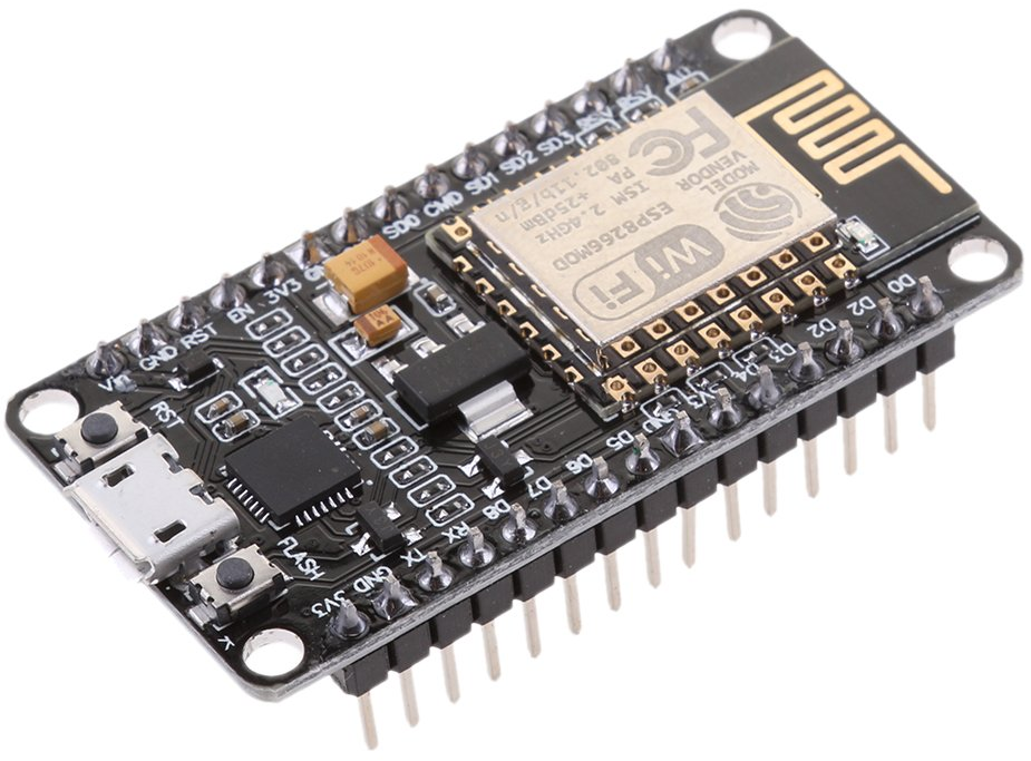
The design is very simple it is based on a ESP8266 development board like:

The circuit has a very few components:
- J1 – a 3 contact terminal strip for power and the output from the RFID reader
- R1 – a 3.3K 1/4 watt resistor
- R2 – a 6.8K 1/4 watt resistor, R1 and R2 protect the input of the ESP8266, which uses 3.3v, from the RFID reader, which uses 5v
- U1 – the ESP8266 component
The follow schematic shows the circuit
 . The PCB design can be found in my GitHub repository
The source code for the ESP8266 can be found in the microcontroller folder of my GitHub repository
At this time the code supports either a ID12LA_Reader or a 7491E_Reader.
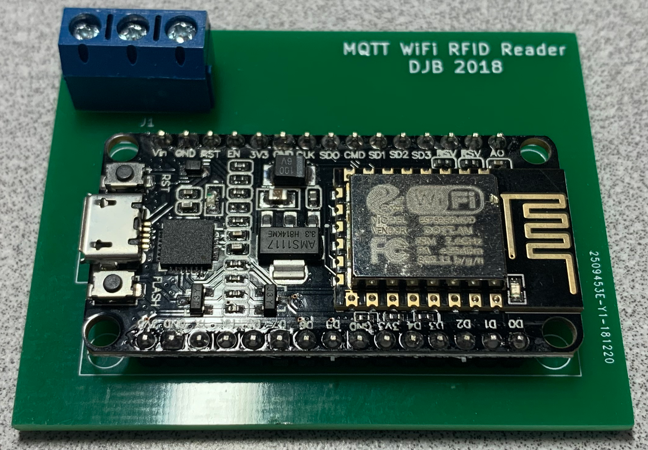
The finished project
