I created a section of track to experiment with various technologies and concepts.
- Track Design
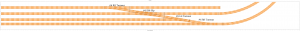
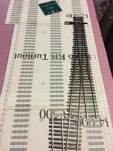
- Created a small track layout using XtrkCad with left, right and double slip switches as seen in the following image.
- Foam Roadbed
- Attached foam to hollow core doors using PL300 Foamboard adhesive. While it certainly stuck the foam to the surface the glue didn’t flatten as much as I would have liked I won’t use that glue for the next section.
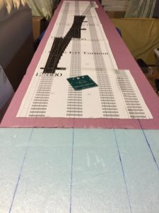
- Printed the track pages in full scale but only the pages that contained turnouts, as the others simply contained straight track and the distance from the edges allowed for straight lines to be drawn on the foam.
- Transfered the design by drawing straight lines and placing the printed layout on the foam with the first two turnouts as illustrated in the following images.
- Embedding Turnout Switches
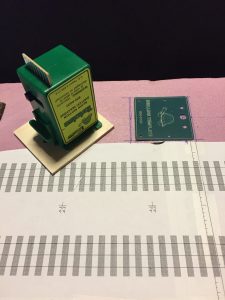
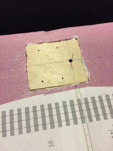
- Cut a piece of 1/8″ thick Baltic plywood larger than the Tortoise switch machine template, drilled holes, as indicated on the template. Using LN-907 Liquid Nails Extreme Heavy Duty adhesive glued the Tortoise switch machine to the plywood. Note the glue is permanent, so it is important the machine is correctly placed.
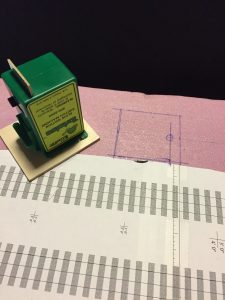
- Marked the turnout throw-bar center on foam, then using the Tortoise template drew a slightly larger rectangle. The Tortoise switch machine glued to the plywood can be seen beside the template and the outline of the hole to be made in the foam in the following images.
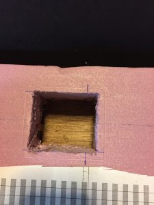
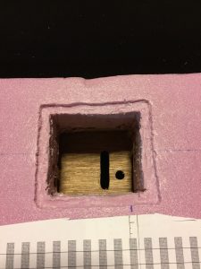
- Created the hole for the switch machine, as shown in the images below. Note the hole goes through the top side of the hollow door plywood surface.
- Used a Dremel tool to route out the depth of the thickness of the plywood and cut a slot for the Tortoise circuit board to protrude through the bottom plywood surface, as shown in the image below. Applied a bead of glue onto the lip and set the switch machine into the hole making sure the cross markings on the plywood aligned with the marks on the foam.
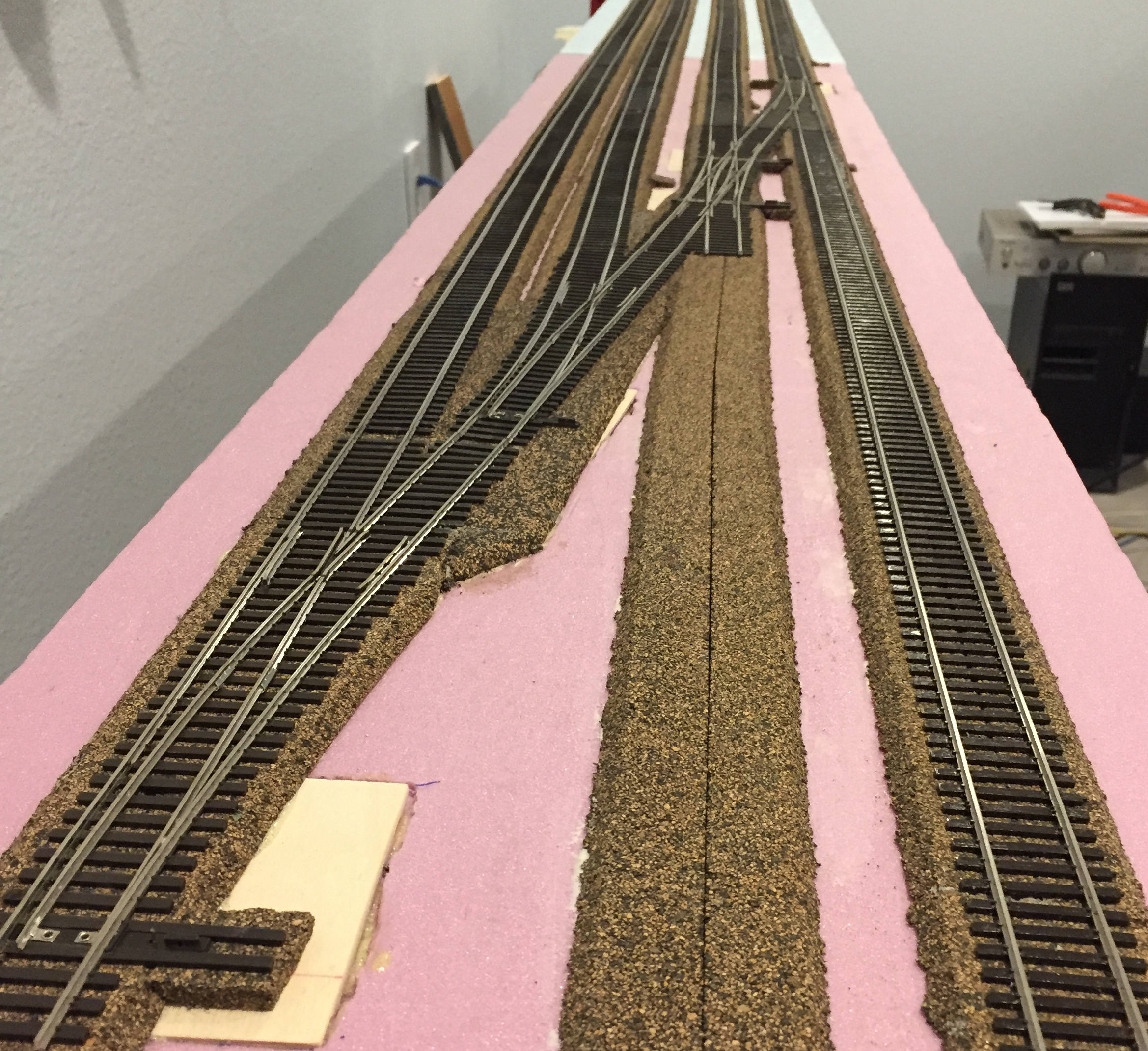
- Cork Roadbed
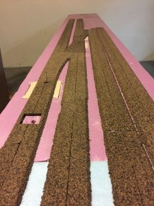
- Using Liquid Nails Extreme Heavy Duty adhesive glued the cork roadbed onto the foam using the straight lines previously drawn as guides and the turnouts as templates for custom cut cork. An inexpensive blade coffee grinder was used to create small crumbles that were used the fill the gaps between some of the cork pieces. Carpenters glue covered the crumbles and after it dried the surface was leveled with coarse sandpaper. The results can be seen in the following picture.
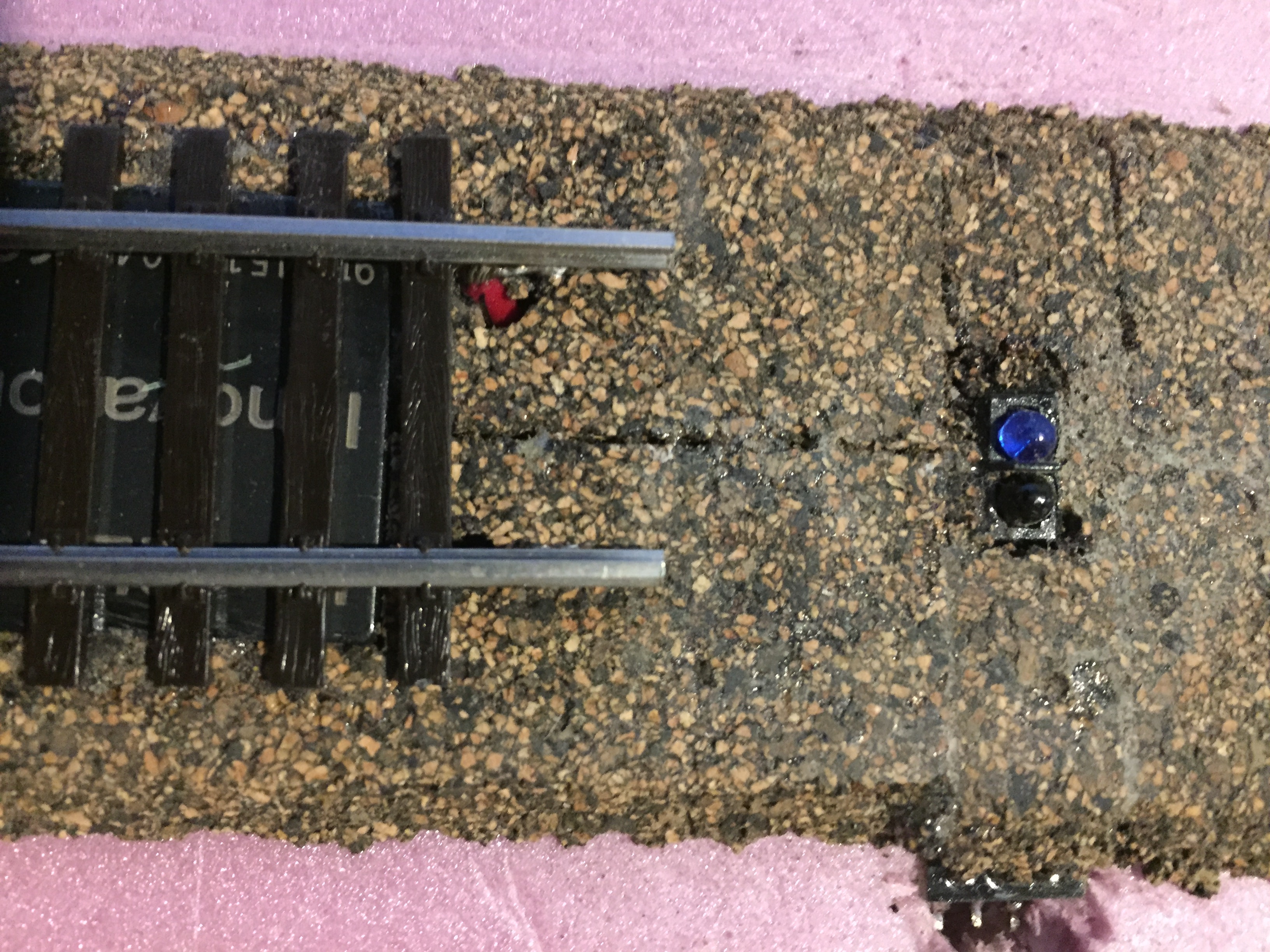
- RFID Reader
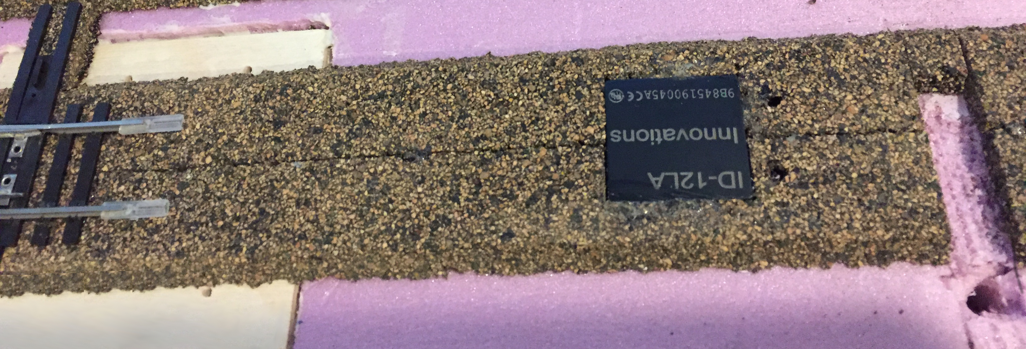
- The hole in the cork on the left in the image above was cut slightly larger than the RFID reader. To ensure the top of the RFID reader was flush with the cork a small amount of the foam was removed. While there are PC boards available to mount the RFID reader on wires were simply solder to the appropriate pins and threaded through a 1/8″ hole under the RFID reader. The space around the RFID reader was filled in with ground cork and carpenter’s glue.
- As it is advisable to not have long pieces of rail that might interfere with the RFID reader the turnout, which was glued the cork roadbed with Gorilla glue the section shown has insulated joiners.
- To the immediate right of the RFID reader the two holes were drilled for the track power.
- The trough found further right was prepared for an IR sensor.
- IR Sensor
- The IR sensor was placed in the trough and then covered with cork as well as ground cork with glue to fill in the spaces. To left of the sensor the RFID sensor visible below the track glued to the cork bed with Clear Gorilla Glue.
- Track
- A number of section of flexible track and turnouts were also glued to the cork road bed using the Gorilla glue.
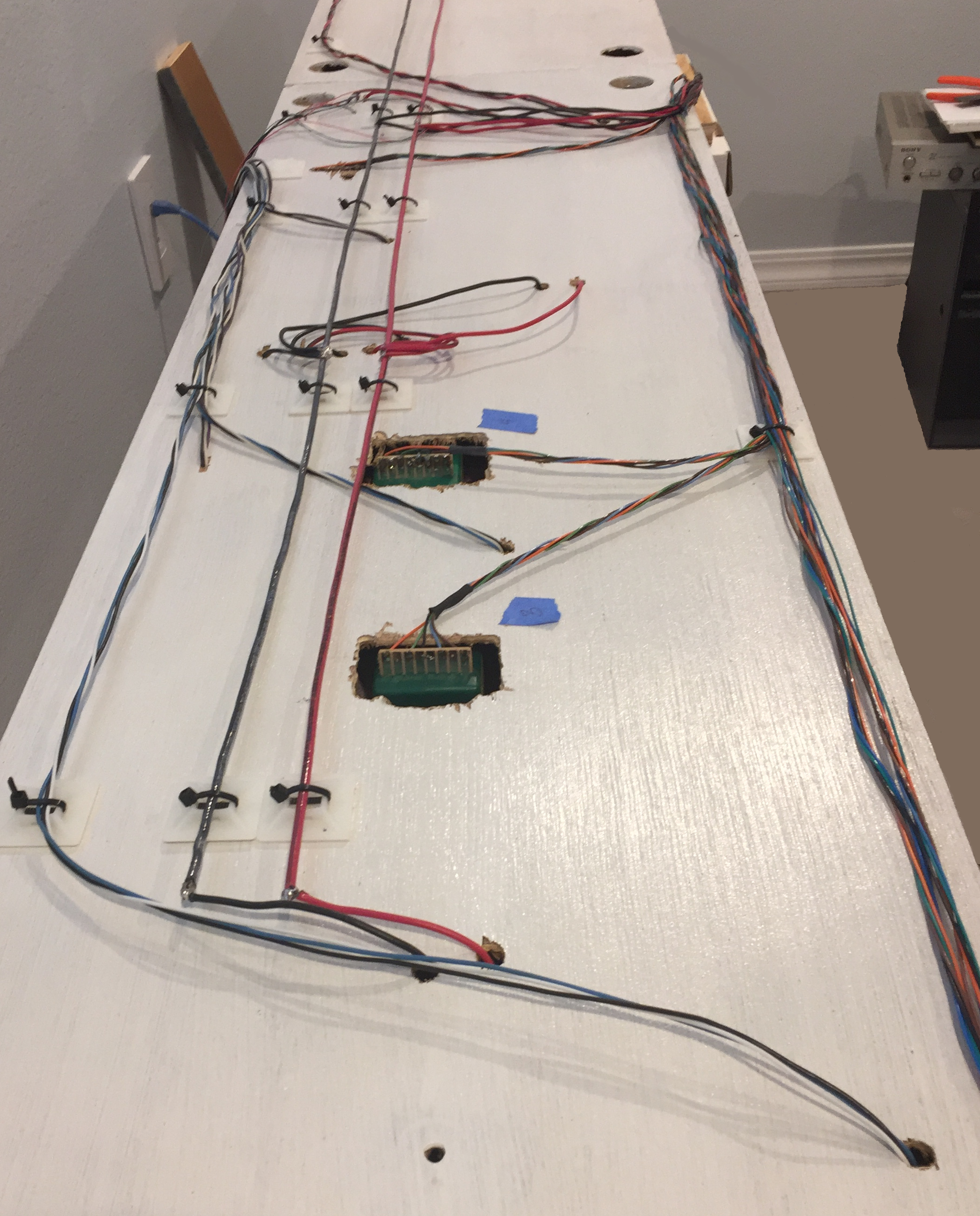
- Wiring
- Rather than working from the bottom, and given the light weight of this section the unit was filliped over and the wiring completed. The 12 gauge wires (red/black) are the DCC bus which feeders are soldered to. The right side has the turnout wires and the left the sensor wiring.
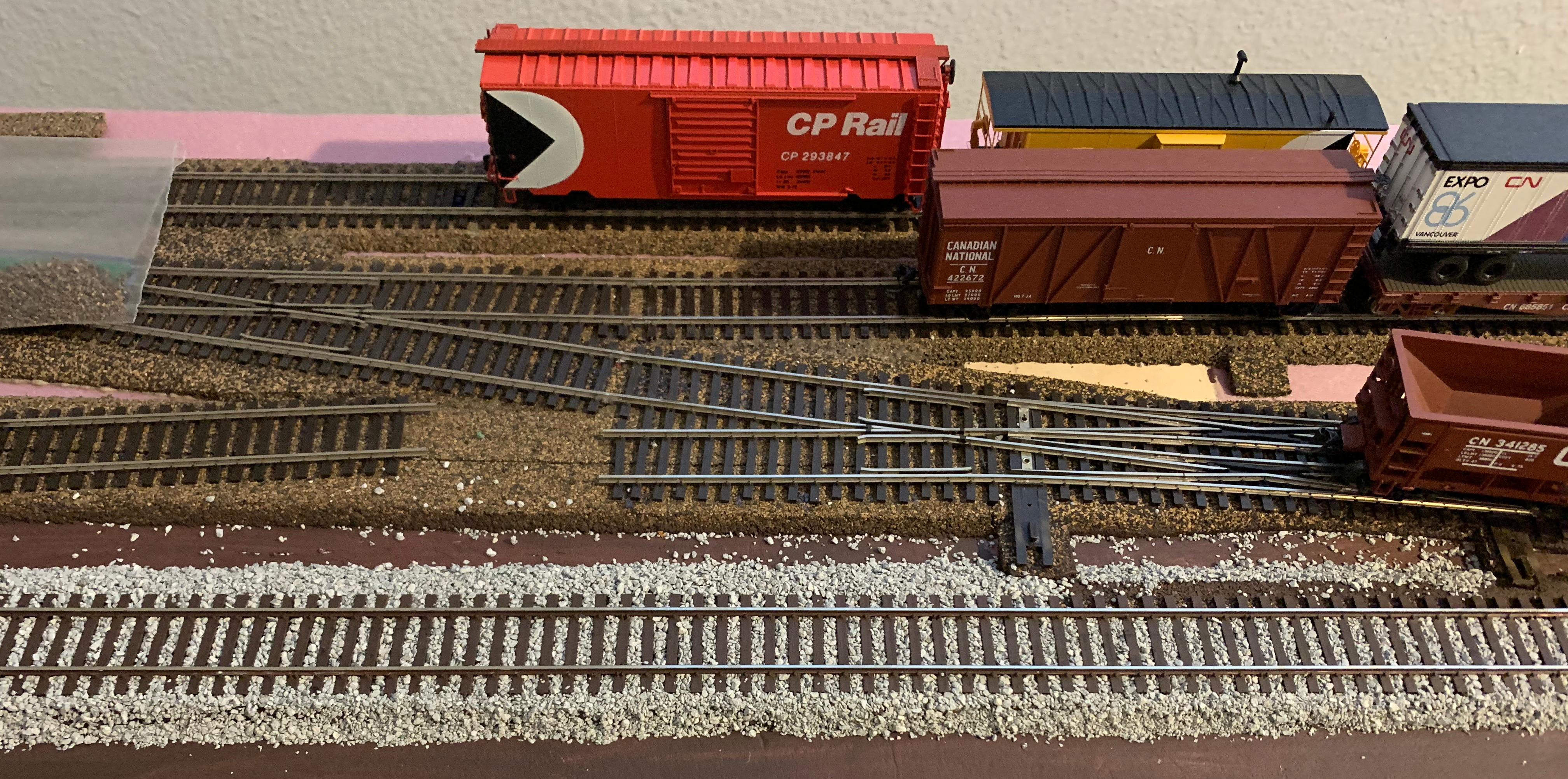
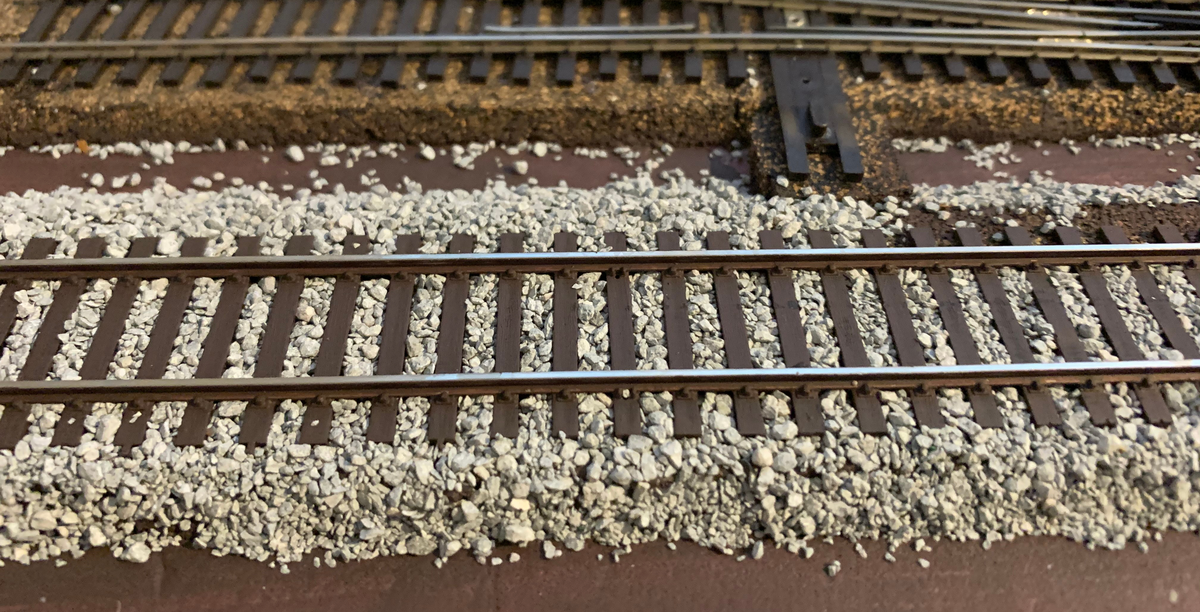
- In keeping with the nature of this module, after viewing many “how to ballast” I decided to try a small section of track
- I painted the track and road bed with a Behr Ultra (MQ2-39) Rare Wood latex paint
- Used Mod Podge full strength on the shoulders and sprinkled on the ballast
- Filled in the ballast on the top surface
- Spritzed the ballast with 50% isopropyl alcohol
- Used a pipette to cover the ballast with 50% Mod Podge solution